Personal project. A small box above the window pulls both curtain panels open and closed with a GT2 belt along the ceiling track. It is controlled from Home Assistant. The motor is one of my 20 kg·cm hobby servos, converted to continuous rotation and driven as a geared DC motor. There are no limit switches. The board works out that the curtain has reached the end of the track by watching the motor current, the same idea as sensorless homing on a 3D printer.
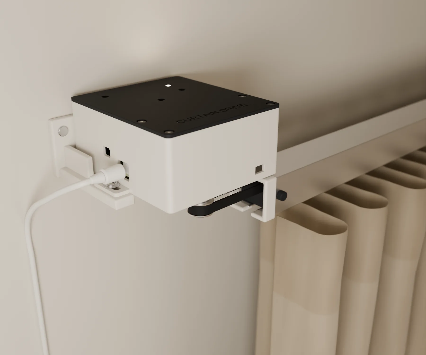
How it will look
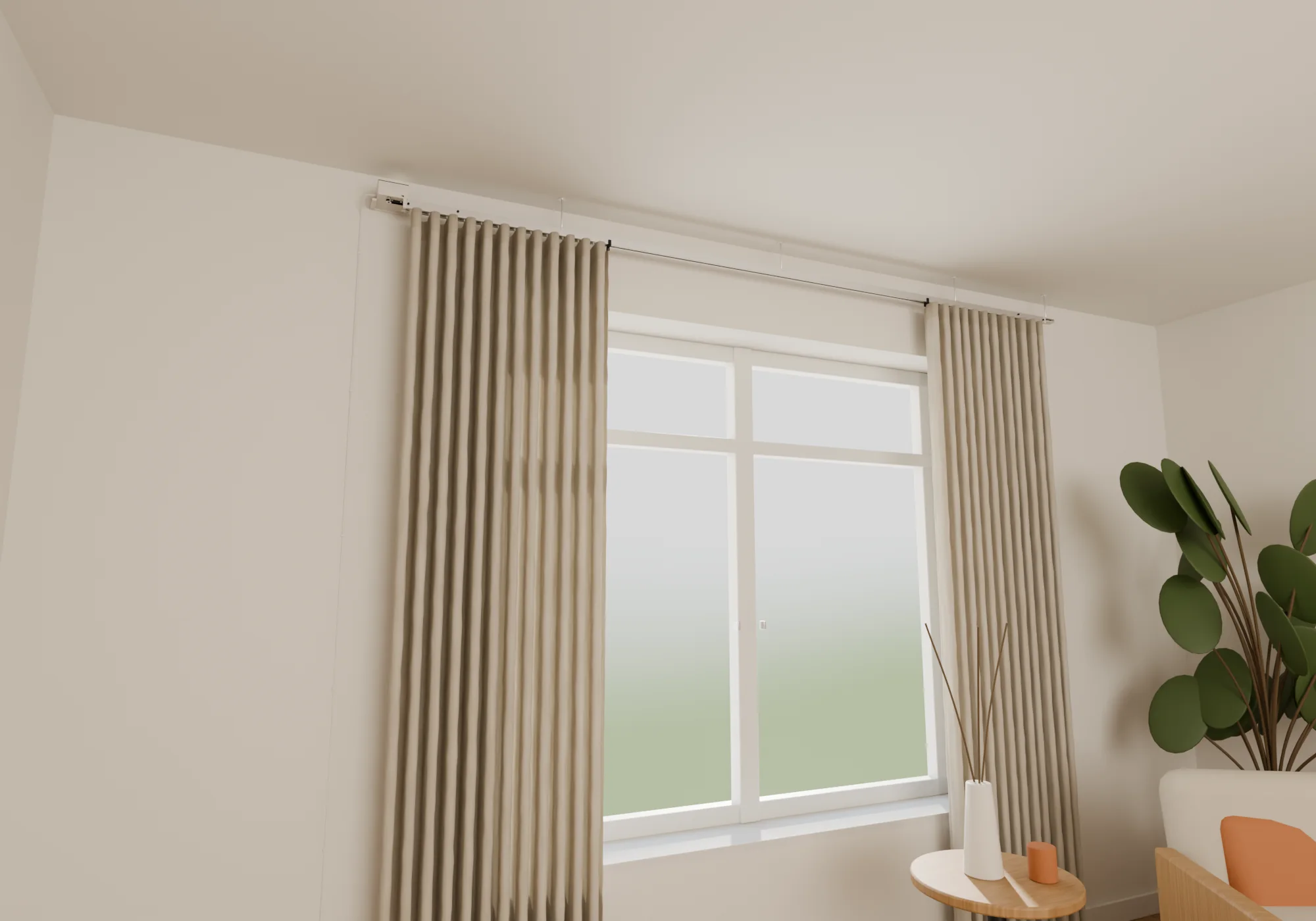
A living-room window with a ceiling-hung track and two linen panels that part from the centre. One motor moves both panels: each panel’s lead carrier clamps to the opposite run of the same belt loop. The box, board and servo are the real design geometry. The room, track, bracket and carriers are illustrative.


How it finds the end stop
A TI DRV8876 H-bridge drives the motor. Its IPROPI pin mirrors the load current at 1000 µA per amp, and a 1 kΩ resistor turns that into 1 V per amp at an ESP32-C3 ADC pin. The firmware (ESPHome) runs a 20 ms loop:
- ramps the PWM in over 300 ms and ignores the start-up current;
- dead-reckons the position from run time and slows down for the last 10 % of travel;
- stops when three samples in a row exceed the stall threshold.
That stall is the end stop. It re-homes the position to 0 % or 100 %, so the time-based estimate resyncs at every end. The hardware current limit (ITRIP, set by a VREF divider) is 2.7 A. The software threshold sits below it on purpose, so the firmware stops the motor before the driver’s own chopping ever engages. The threshold is still a placeholder at 1.8 A. It has to be set from logged running and stalled current once the board exists.
A 12 V barrel jack powers the motor. An AP63203 buck makes 3.3 V from 12 V or from USB-C, which is also the ESP32-C3’s native USB for flashing. A second ADC input watches the 12 V rail.
One copper layer, no vias
I mill or laser my own boards. This one is for an xTool F1 Ultra fiber laser (following sphawes’ fiber-laser PCB process), which etches one side only. So the whole board is on F.Cu with zero vias, and anything that would normally cross on the bottom layer has to go somewhere else.
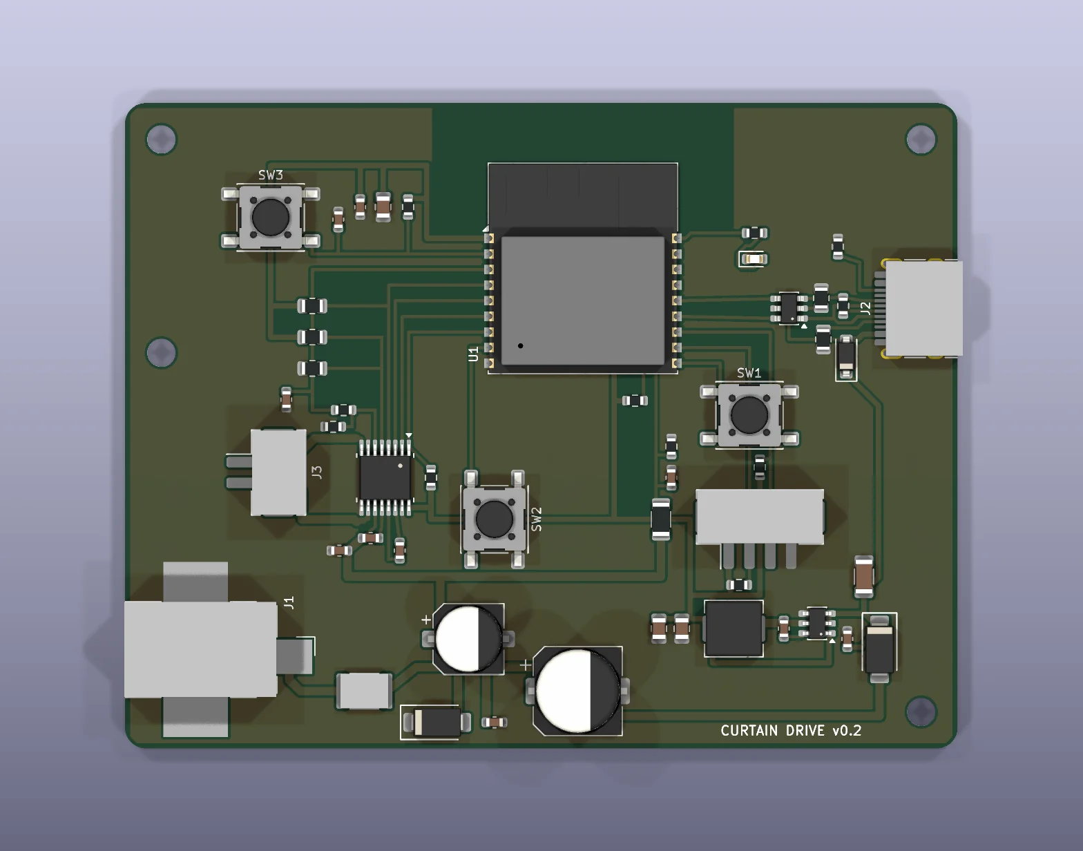
The first redesign was a sensible-looking placement handed to the autorouter. It left 15 connections open. Every one of them came back to crossings that a single layer cannot make. What closed the board was planning the topology first:
-
Choosing GPIOs for the layout. The ESP32-C3 pins are freely assignable. The four driver lines run out of the module’s left edge in the reverse of the driver’s pin order, so they fan straight into it. Current sense sits on the one ADC pin on that same edge.
-
Letting parts carry crossings. Several resistors sit across a track, which passes between their pads:
- R1 (1206) over the 3.3 V supply;
- three 0805s over the current-sense line, including the VREF divider;
- one 0805 over VBUS.
The tact switches’ paired pins are connected inside the switch, so a switch passes its signal and ground across the track under it. The driver’s exposed ground pad joins its ground pins on both sides.
-
Going under the module. The ESP32 module’s 3.3 V pin is fed from underneath, between its pad rows and its centre ground pad.
-
USB-C. The receptacle’s pad row runs D+, D−, D+, D−, so one crossing is unavoidable. That, and the ESD chip’s boxed-in ground pin, are the only two 0 Ω jumpers on the board. Only one of each VBUS and GND pad pair is wired, because every USB-C plug ties those pins together internally.
A Python script places every part, lays a locked skeleton of the tracks that decide the topology, and then lets FreeRouting fill in the rest on a one-layer board. KiCad’s DRC finishes at 0 violations, 0 unconnected items and 0 schematic mismatches, and the result held across repeated routing runs.
What went wrong and how it was diagnosed
- The autorouter walled off the module. On the first attempt, FreeRouting joined the 3.3 V parts in the corner by running a track straight down beside the module. That cut off every pin on its left edge. The fix was to pre-route the supply through the module’s own pin from underneath, so the router had no reason to build that wall.
- A “no vias” setting that silently routed nothing. The documented trick for single-layer routing, injecting a
(vias off)settings block into the design file, made FreeRouting 2.4.1 report zero routable pins. It finished in four seconds with an empty result. Exporting the same board without the block showed the pins were fine. A one-copper-layer board already has nowhere to put a via, so the block was dropped. - Connections that would not join a fixed track mid-way. Most of the last failures were short stubs: a pull-up or capacitor that had to join a pre-routed track partway along its length. The router would not make those joins, so each one became part of the pre-routed skeleton.
- Ground islands that came and went. One run left the output capacitors’ ground walled in by the 12 V feed and the buck’s feedback track. The previous run had happened to route the 12 V feed another way. Pinning the 12 V routes made the result stop depending on the router’s luck.
- A USB-C socket that would not have seated. Checking the exported 3D board inside the enclosure model showed the receptacle’s mouth 0.3 mm inside the board edge. A plug’s overmould would hit the PCB before mating. The connector now overhangs the edge by 0.5 mm.
Printable enclosure
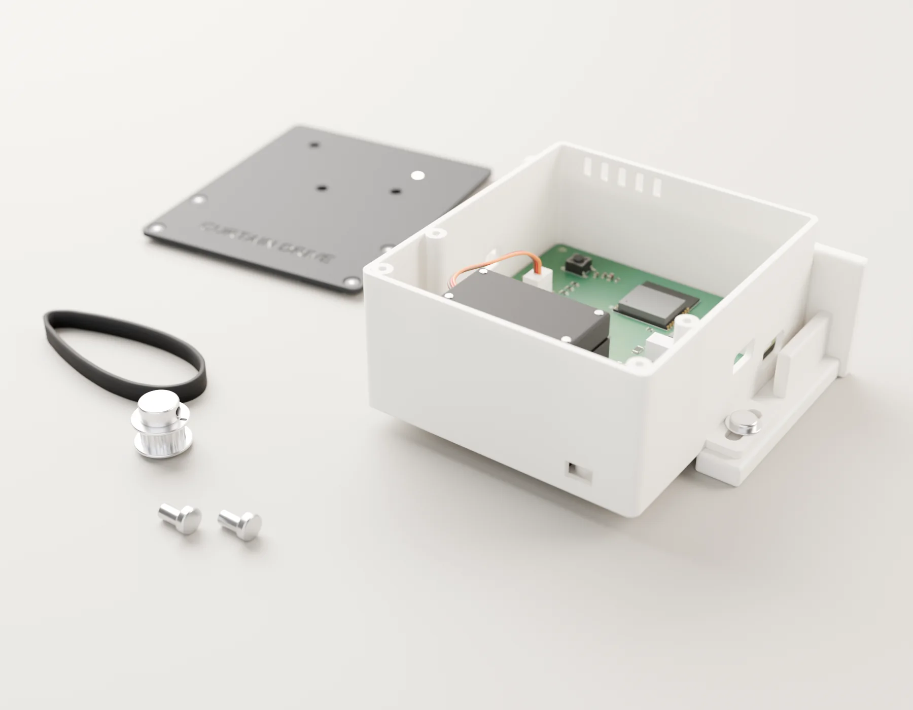
The enclosure is modelled in Blender from a parametric script: a base holding the board and the servo, shaft down through the floor to the belt pulley, and a screw-on lid. The populated board is imported from KiCad as a 3D model. The script checks that each printed part is a single watertight solid, and that nothing collides with the lid closed. The jack and USB-C openings are sized for the plug overmoulds, not only the connector bodies.
Status
Designed, not built. The board has not been etched, and the firmware has not run on hardware. Still to do:
- measure the actual servo with calipers (the enclosure uses its datasheet dimensions);
- make and assemble the board;
- log the real motor current to set the stall threshold.
The ESP32 firmware and much of the layout scripting were written with AI to my spec. I set the requirements, reviewed the design decisions and will verify it all on the bench.
Tools and skills
KiCad 10 with Python-scripted schematic and board generation, FreeRouting, single-sided DFM for laser fabrication, TI DRV8876 current sensing, ESPHome on the ESP32-C3, Home Assistant, Blender scripting for enclosure design and verification, and FreeCAD for placeholder STEP models.