What it is
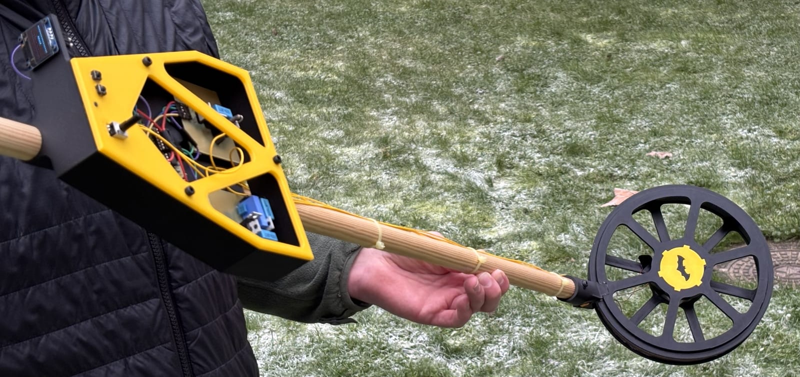
A working VLF (very-low-frequency) induction-balance metal detector, built for DTU’s 34621 Electromagnetic Sensors & Digital Signal Processing course. A transmitter coil is driven at 2 kHz; a receiver coil picks up the field re-radiated by nearby metal; and the firmware runs a single-bin DFT on the sampled receiver signal to recover its amplitude and phase. The phase is what matters — it’s how the detector distinguishes ferrous from non-ferrous metal, not just “there’s something there.” Output goes to an OLED HUD and a variable-tone buzzer.
This was a group project — the four of us built it together, across the DSP firmware, the coil/driver electronics, and the board.
How it works
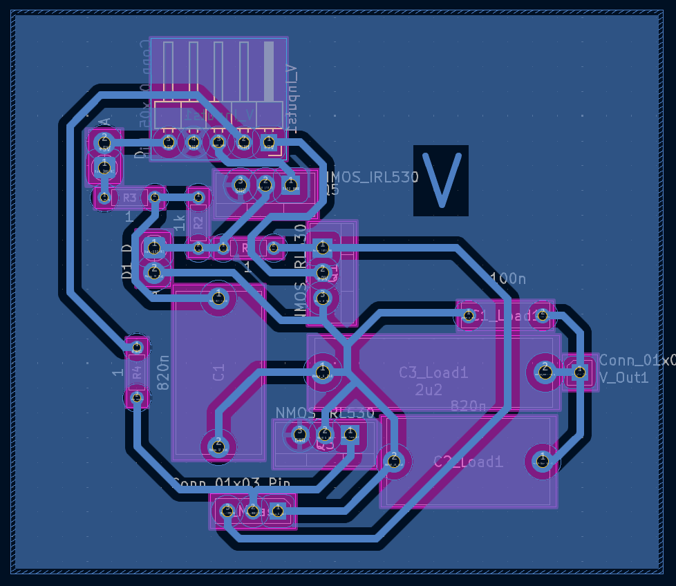
- Transmitter: an H-bridge (IRF5305 / IRL530) drives the TX coil with a 2 kHz square wave.
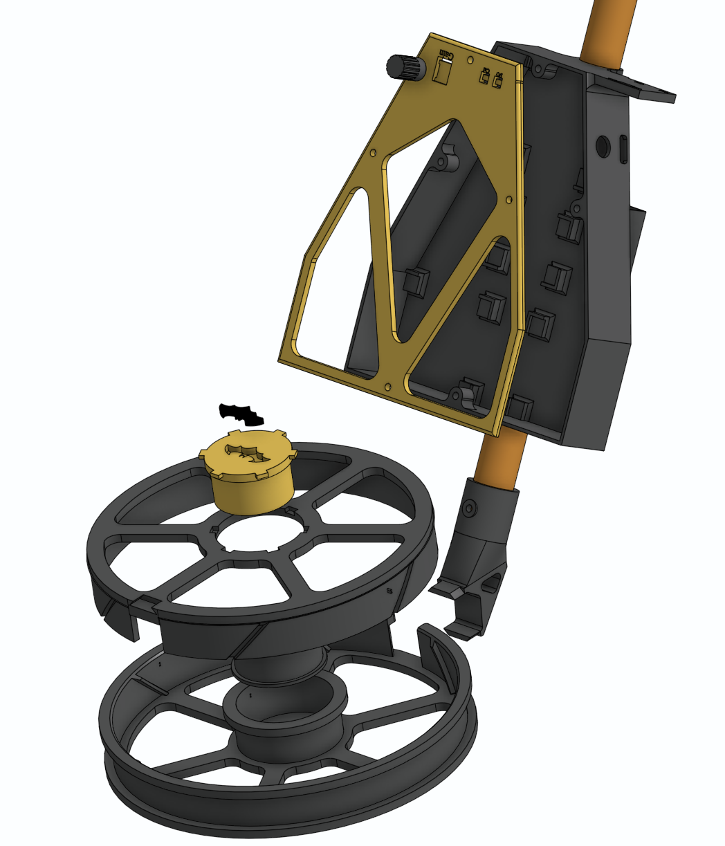
- Coil head: concentric TX/RX coils in a bucking configuration — a small opposing coil cancels the direct TX→RX coupling so the receiver sees (ideally) only the field from the target.
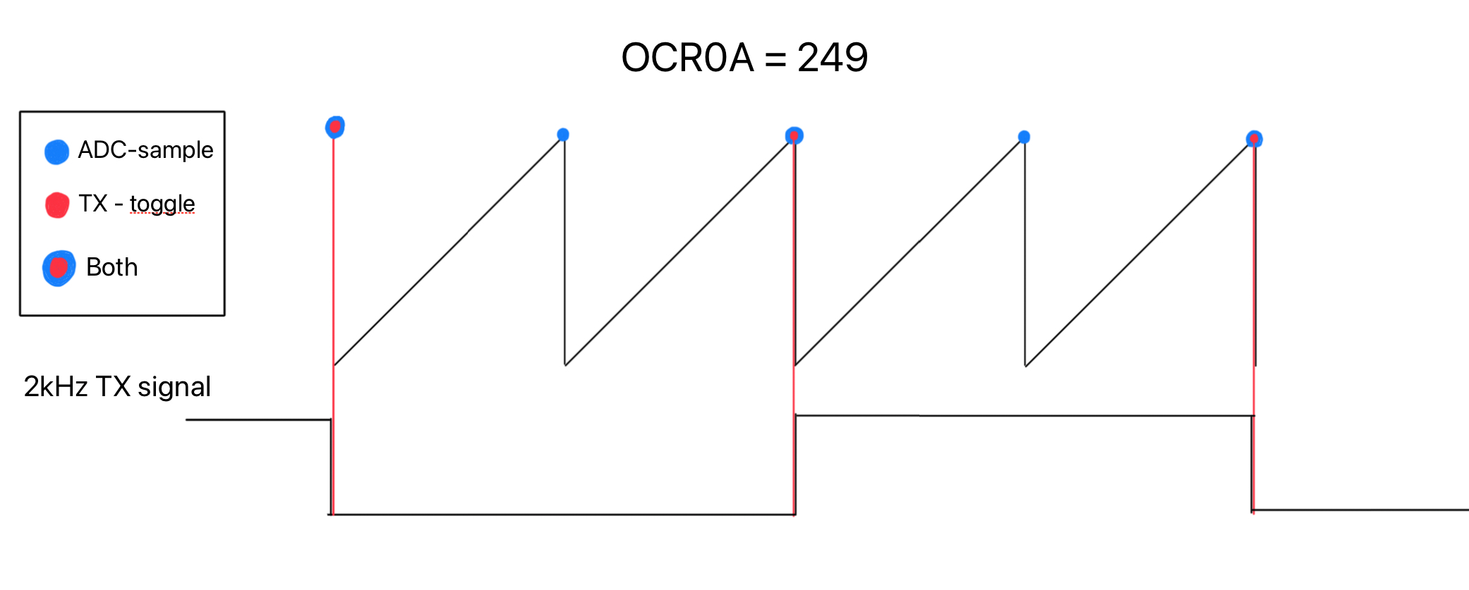
- Acquisition: the 10-bit ADC samples at 8 kHz — 4× oversampling of the 2 kHz carrier, coherently locked to the drive so each DFT window lands on whole cycles.
- DSP core: a single-bin DFT (a Goertzel-style evaluation at just the carrier frequency) gives the in-phase and quadrature components, from which amplitude and phase are computed every window. An IIR smoother tames the noise before the phase is classified.
- Feedback: an SSD1306 OLED shows a live readout; a buzzer changes tone with proximity.
The hard parts
The whole detector lives or dies on two things, and neither is in the textbook:
- Nulling the bucking coil. Induction balance only works if the direct TX→RX coupling is cancelled to near-zero, so the tiny target signal isn’t buried under a huge carrier. Getting the concentric coils and the bucking winding physically balanced — and keeping them balanced — is fiddly, and any residual imbalance sets the noise floor for everything downstream.
- A phase reading that doesn’t wander. Single-bin phase detection is only clean if the sampling is coherent with the drive; drift or a non-integer number of cycles per window makes the phase jitter and the ferrous/non-ferrous decision flicker. Locking the 8 kHz sampling to the 2 kHz drive (4× oversampling) is what makes the phase stable enough to threshold on.
Results
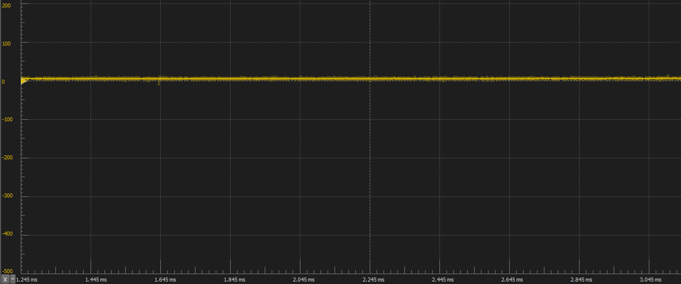
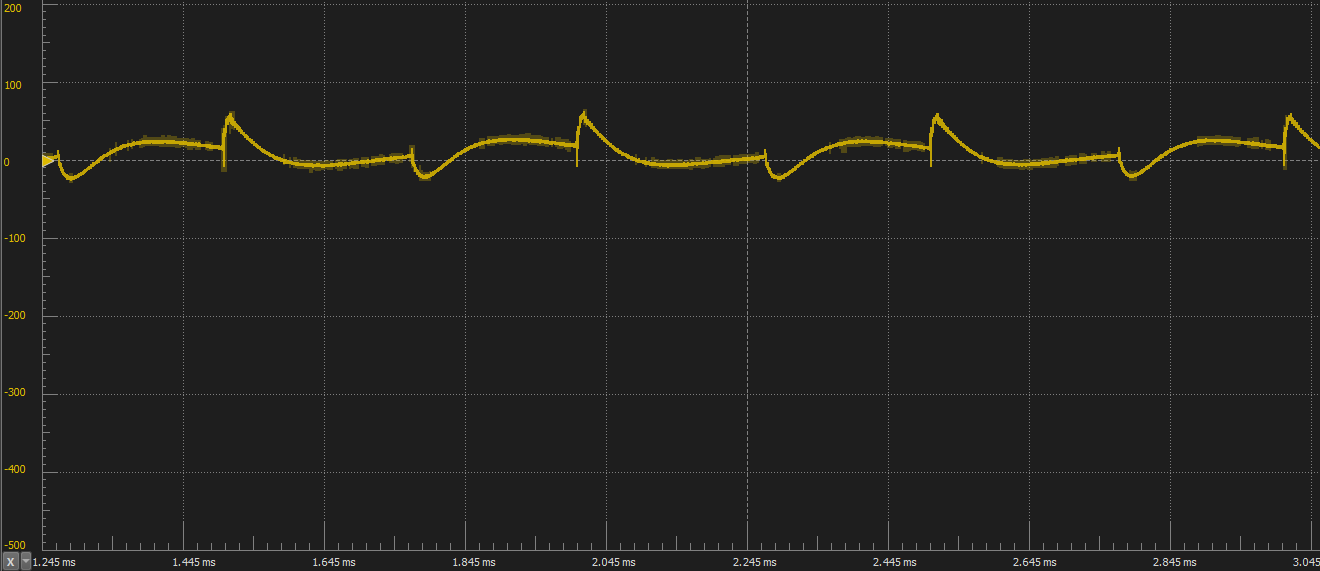
A functioning detector that responds to metal and separates ferrous from non-ferrous targets by phase, with a live OLED readout and proximity tone. The clearest evidence is on the bench — the received-coil signal barely moves over an empty coil, then shifts distinctly when metal enters the field:
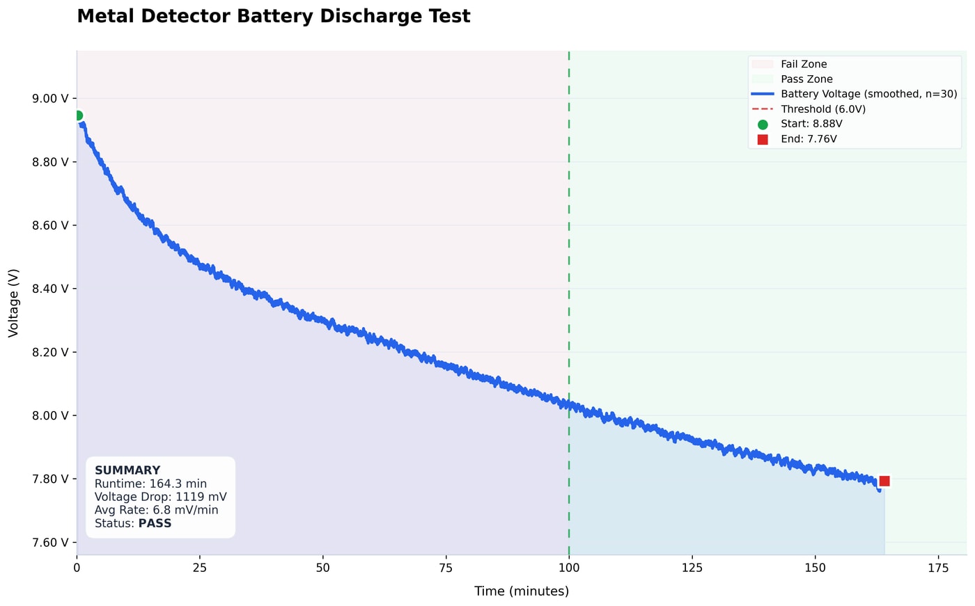
Because a detector is only useful if it runs in the field, we designed the power path for endurance rather than raw drive. The MCU sleeps between DFT windows instead of busy-waiting, and the coil is driven by an efficient MOSFET H-bridge (IRF5305 / IRL530) rather than a lossy linear stage — so most of the battery’s energy goes into the transmit field, not into heat. A bench discharge test confirmed it: ~164 minutes (2 h 44 m) of continuous operation on a single charge, the pack sagging only from 8.88 V to 7.76 V and never nearing the 6.0 V cut-off.
Full write-up in the project report (repo), with the KiCad hardware, LTspice/QSPICE validation, and MATLAB/Python analysis alongside the firmware.
Interactive project dashboard
We kept a live dashboard for the project on GitHub Pages — a filterable Gantt timeline, milestone tracker, the responsibility split across the four of us, the tech stack, and a full image gallery of the 3D models, boards, and scope captures:
Tools & skills demonstrated
Real-time embedded DSP on an 8-bit MCU (single-bin DFT, coherent sampling, IIR filtering), induction-balance sensor design, power electronics (H-bridge coil driver), KiCad hardware, and SPICE validation — the electromagnetic-sensing and signal-processing core of course 34621, on real hardware.