What it is
A complete little oscilloscope-plus-signal-generator system built for DTU’s 30082 Projektarbejde i Digitalteknik, spanning three devices that talk to each other:
- an ATmega2560 that samples analog signals (ADC) and acts as the oscilloscope front end,
- a LabVIEW GUI on the PC that plots the captured waveforms and sends control commands,
- a Basys 2 FPGA that generates waveforms on command, driven over SPI from the MCU.
The MCU is the hub: it streams sampled data up to LabVIEW over UART, receives waveform settings (shape, frequency, amplitude) back down, and forwards them to the FPGA over SPI. The FPGA synthesises the waveform via PWM, which an active low-pass filter turns back into a clean analog output.
A group project spanning the MCU firmware, the FPGA VHDL, the protocol, and the analog output filter.
How it fits together
- MCU ↔ LabVIEW (UART, 115200 8N1): a framed binary protocol —
0x55 0xAAsync bytes, a length field, a type byte, payload, and a 16-bit checksum — carries button/switch events, oscilloscope settings, Bode-plot requests, and an SPI stress test. - MCU → FPGA (SPI): waveform commands are forwarded to the Basys 2, which generates the requested signal.
- FPGA → analog (PWM + filter): PWM output through a designed active low-pass filter (verified in LTspice, with the filter maths worked in Maple) reconstructs the analog waveform.
The hard parts
- A UART protocol that survives real bytes. Streaming sampled data at 115200 baud while also accepting control frames means the receiver has to resynchronise reliably — hence the
0x55 0xAAframing, explicit length, and checksum. Without them, one dropped byte desyncs the stream and the plot turns to noise; a dedicated SPI/stress-test message type exists precisely to shake those faults out. - Two clock domains and two protocols in one MCU. The ATmega2560 is juggling ADC sampling, UART in both directions, and SPI to the FPGA, largely on interrupts. Keeping the sampling cadence steady while servicing comms is the part that takes care.
Results
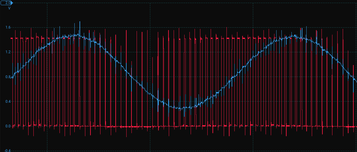
An end-to-end instrument: capture a signal on the MCU, watch it live in LabVIEW, dial in a new waveform, and have the FPGA generate it back out as clean analog — with the protocol, filter design, and verification documented in the project report.
Tools & skills demonstrated
Cross-device embedded integration (C on the ATmega2560, VHDL on the Basys 2, LabVIEW on the PC), robust serial protocol design (framed UART + SPI), interrupt-driven firmware, and active-filter design verified in LTspice/Maple.