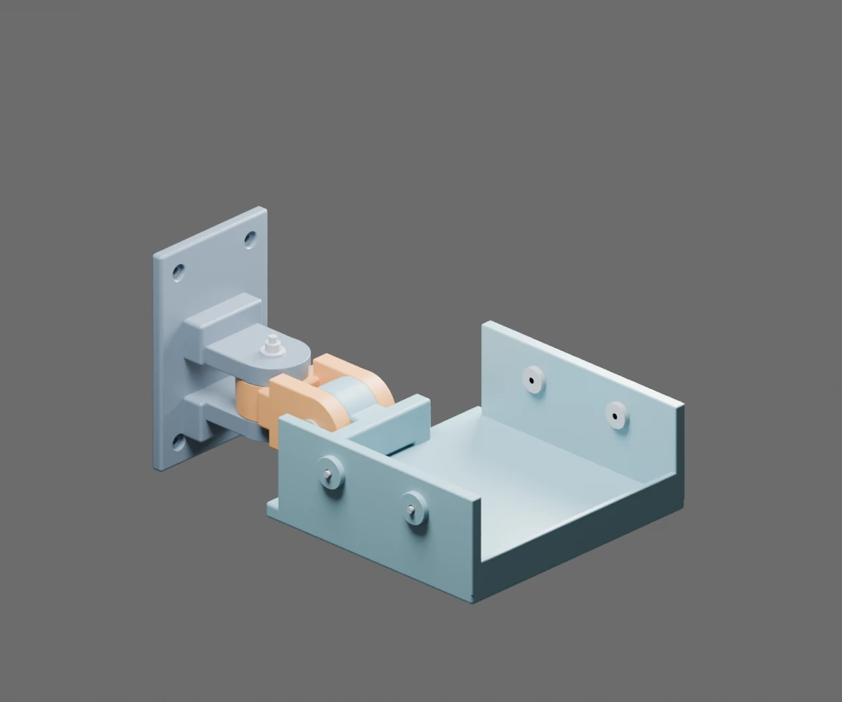
Personal project. I designed a compact wall mount for surround speakers, with separate pan and tilt joints and a padded cradle that holds the cabinet without drilling into it. The same three printed parts serve either side of the room.
Explore my dorm room and the rail-mounted surrounds in interactive 3D →
How this will look
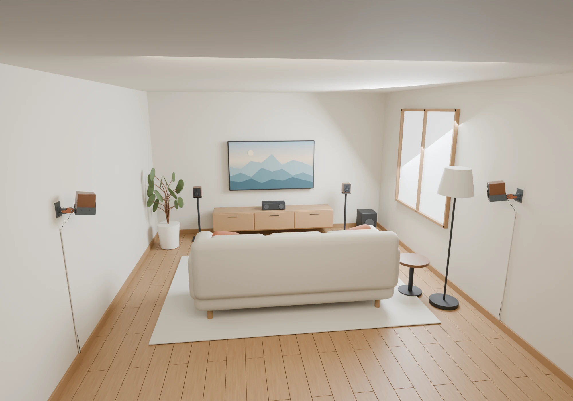
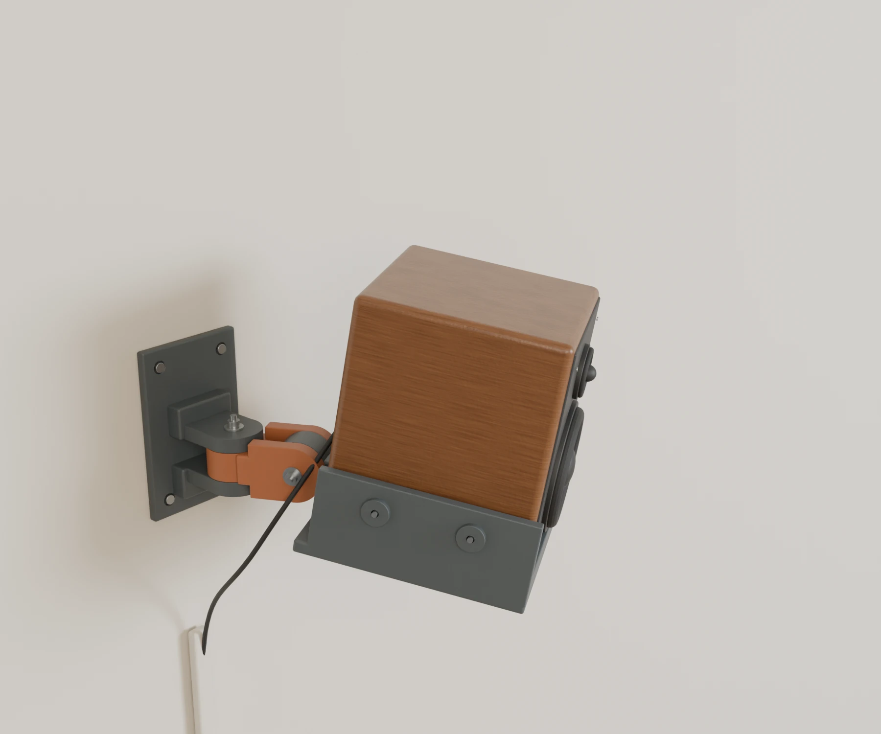
A living-room surround setup with the TV and front speakers ahead of the couch, and the two wall-mounted surrounds behind it. These Blender renders use the actual mount geometry and illustrative walnut speakers sized to the design’s 150 × 150 × 180 mm cabinet envelope.

Explore the Blender scene and render script →
Making room for the speaker and its cables
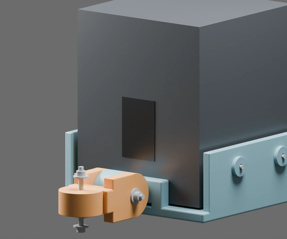
The default cabinet is 150 × 150 × 180 mm, with a designed range of ±60° pan and 30° downward tilt. A wall plate carries the vertical pan joint; a short connecting arm supports the horizontal tilt joint and cradle. Both use M5 bolts, while four M4 swivel-pressure screws retain the cabinet against padding.
FreeCAD generates the solid models from spreadsheet-linked parameters. Python scripts build the geometry, export STEP and print-oriented STL files, and check clearances. A separate Blender assembly provides renders and interactive posing. FreeCAD also has live mouse controls for aiming the assembly.
Positive engagement for the tilt joint
The up/down pivot now has 72 mating radial teeth for 5° increments. The pan pivot stays smooth and continuously adjustable. A recessed ring in the arm mates with a raised ring on the cradle, so tilt position is held by tooth engagement as well as the bolt keeping the faces together.
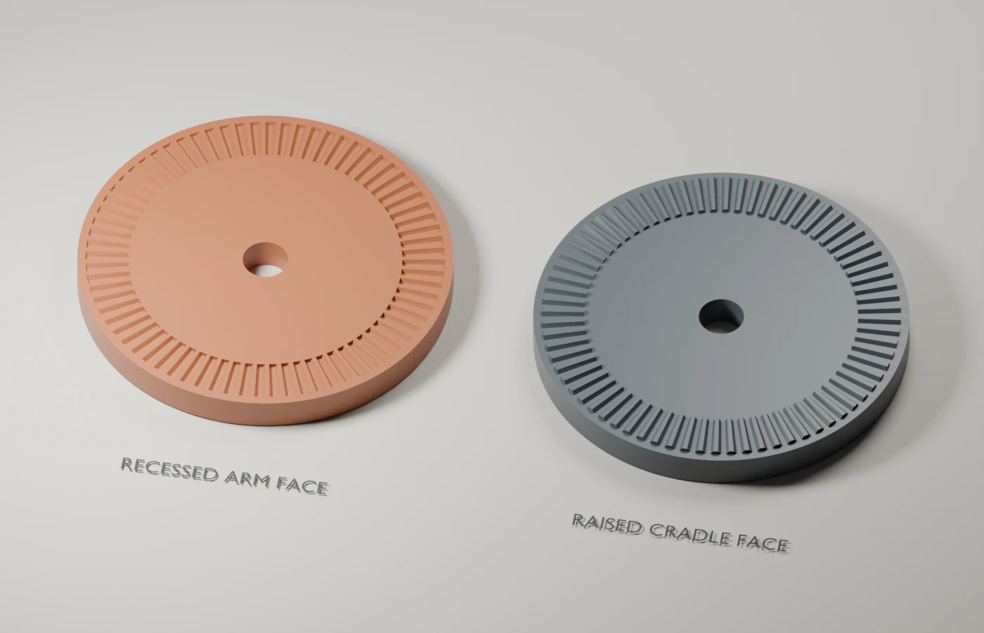
Only one tilt face is toothed. With the bolt loosened, the cradle can slide toward the opposite smooth cheek to disengage, turn to the next setting and seat again. The nominal release travel from seated is 0.6 mm, with 0.15 mm tooth-tip clearance when released.
CAD checks cover all seven tilt settings, confirm that half-step positions interfere when seated, and check 61 released positions. Small printable fit coupons use the same tooth profiles. Printed fit, tooth strength, wear and any improvement in rigidity still need physical testing.
What needed redesigning
The first version put the speaker too far from the wall. Shortening the pivot spacing from 100 to 55 mm brought the cabinet’s rear face from 197 to 147 mm away from it. The connecting arm became shorter and wider, while the rear support was lowered to leave room for the terminal panel.
That reduction had a limit: the wide cradle still needs to clear the wall at full pan. The CAD checks sample 91 pan/tilt positions, including a provisional terminal-and-plug envelope. Terminal-panel height and plug projection still need confirmation against the actual speaker.
Lowering the tilt pivot also changed the gravity lever arm. The load calculations were updated for the new geometry; a smaller mount alone does not establish better holding performance.
Results and current status
- Three printable parts, with editable FreeCAD and Blender assemblies, STEP exports, a hardware list and print instructions.
- CAD checks report valid single solids; parameter checks exercise all six spreadsheet dimensions individually.
- Blender exports report one connected component and zero nonmanifold edges per part. All six STL exports were also re-imported into FreeCAD and checked as closed solids.
- Sampled clearance checks retain the intended motion range. They do not prove continuous clearance or account for flexible cables and deformation.
Current status: The CAD prototype is ready for first-print fit checks. Speaker mass, wall fixings and long-term joint holding performance remain unverified; no safe working load has been assigned.
The project combines parametric CAD, Python geometry automation, articulated assemblies and design for 3D printing.