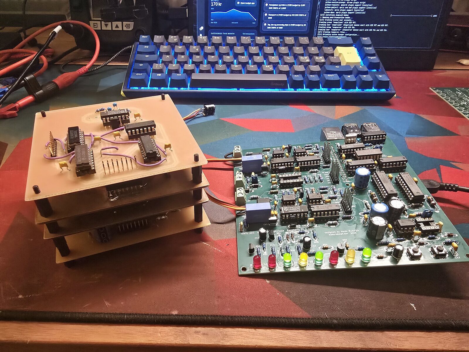
Personal project. I designed the converter, simulated its analog behavior, and split the circuit into four boards that could be milled in-house. With PCBWay sponsoring fabrication, it is now one four-layer board that the Raspberry Pi plugs into.
Rev D: made by PCBWay
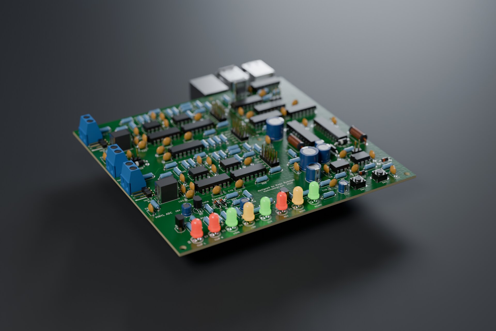
One board, four layers, made by PCBWay, and the best-measuring version of this converter so far.
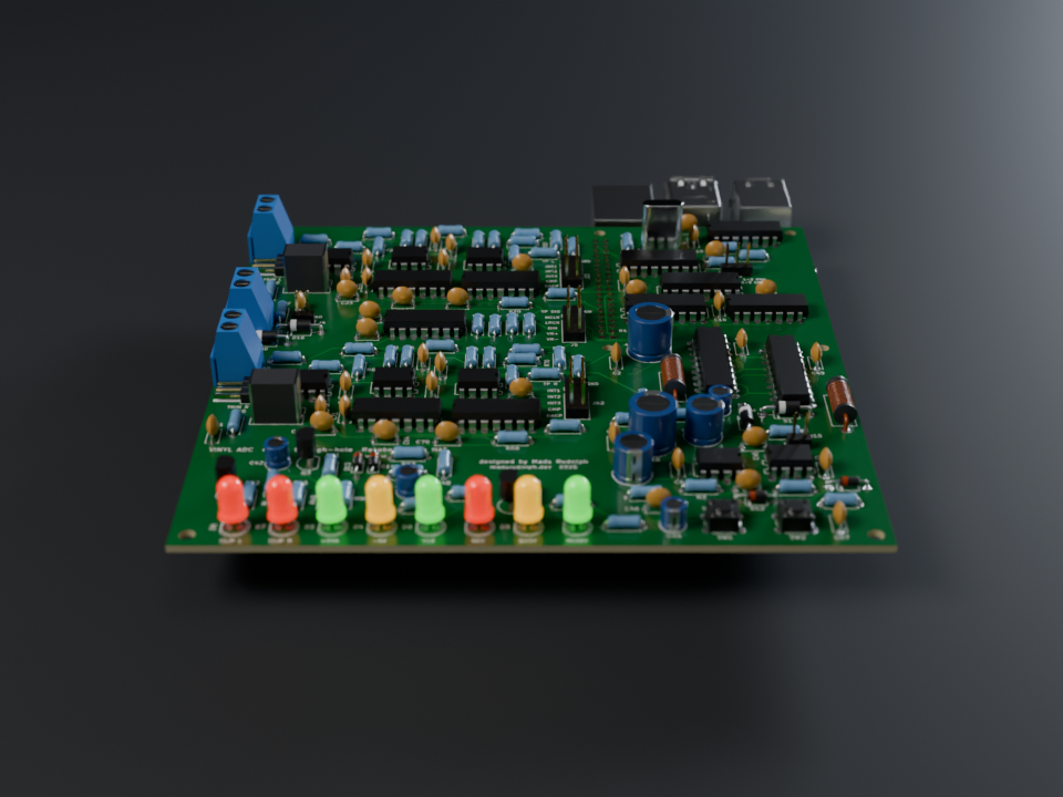
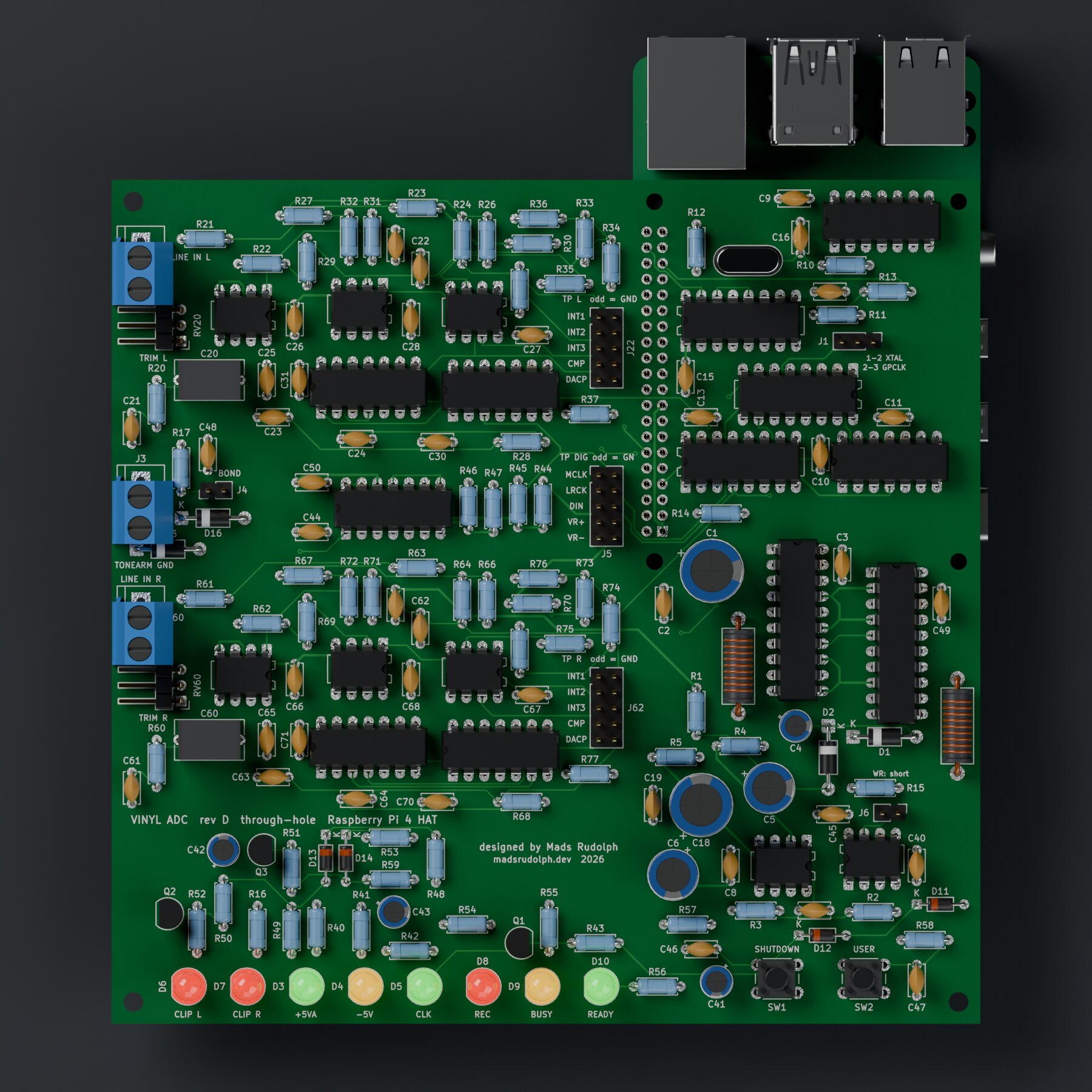
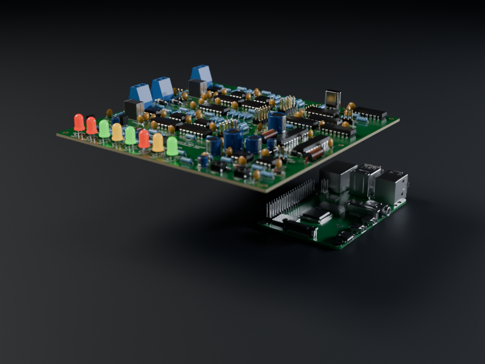
Every board before this one was isolation-milled single-sided, which is why the converter was four stacked boards with dozens of wire links, and why its first bring-up spent a day on a supply rail that reached one board only through solder wicked up an unplated hole. When PCBWay offered to sponsor the fabrication, I could finally draw the converter the way a mixed-signal circuit wants to be drawn: one board, a solid ground plane, an analog supply island behind its own choke, status LEDs, and the Pi as a HAT underneath. I’m grateful to PCBWay for that; this section is about what their boards did for the project.
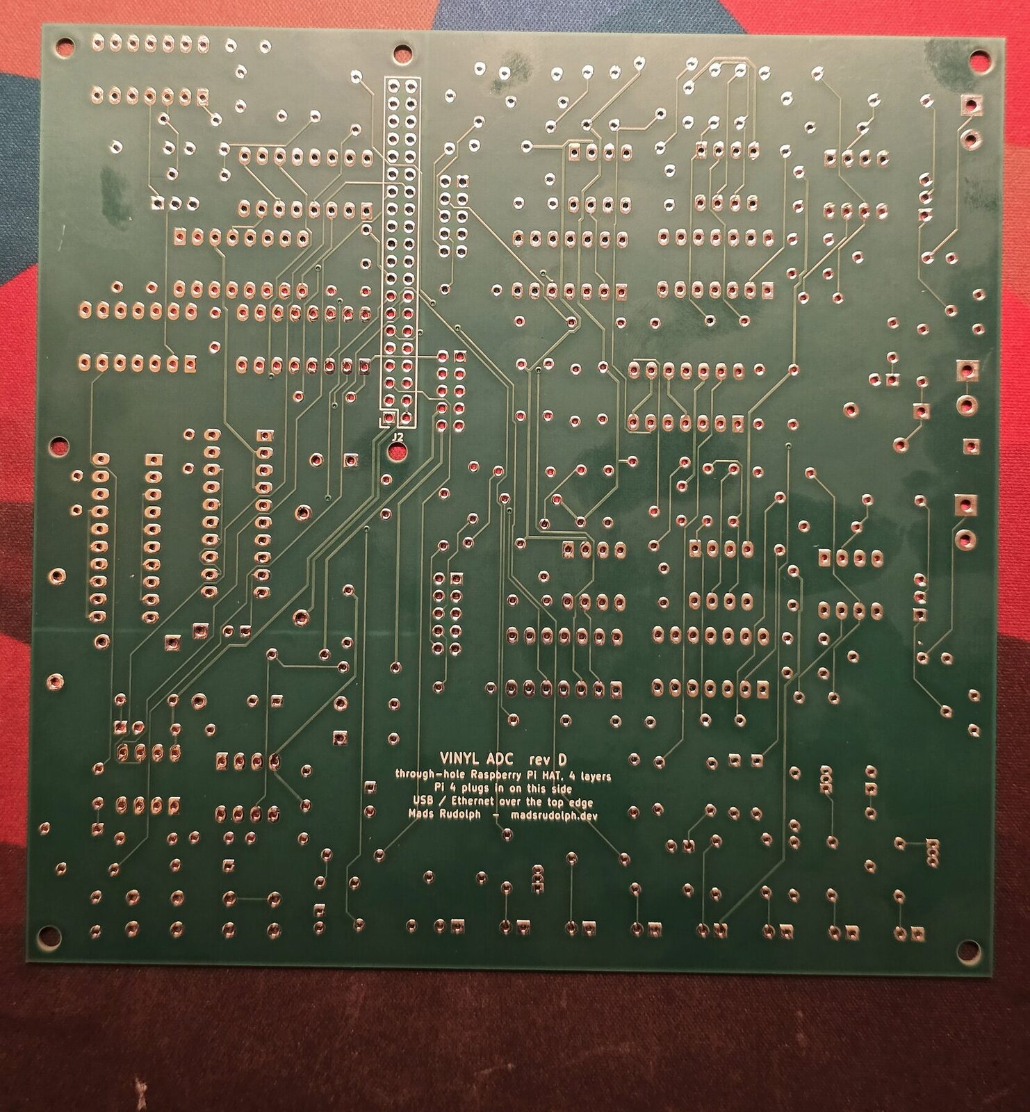
What PCBWay made
| Rev D, per board | |
|---|---|
| Stack-up | 4 layers with a solid ground plane, 1.6 mm FR-4, 1 oz copper |
| Finish | solder mask both sides, white silkscreen, HASL lead-free |
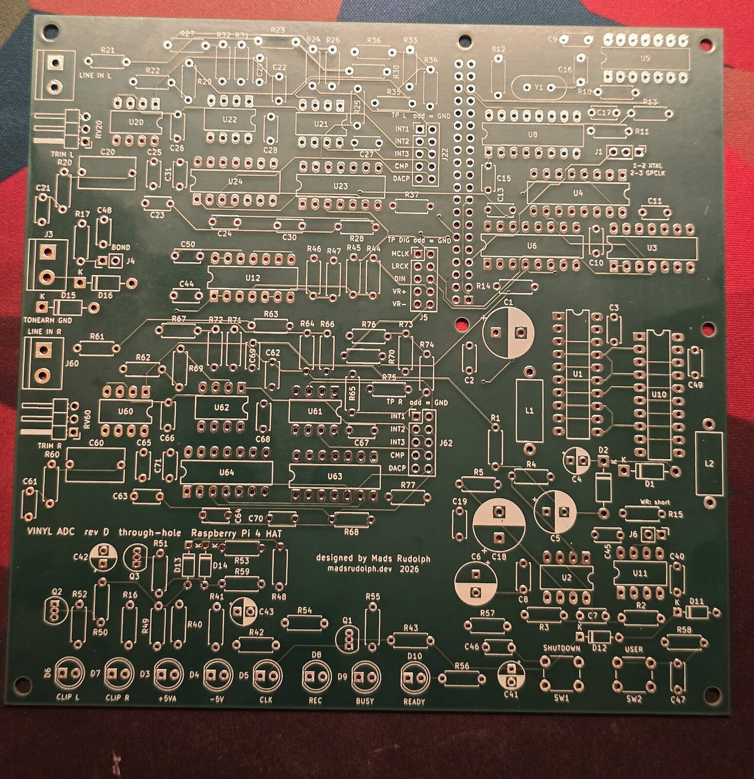
| Holes | 649 plated barrels: 636 through-holes and 13 vias, on each of five boards |
| Routing | 1,020 tracks, the narrowest 0.25 mm; drills down to 0.4 mm |
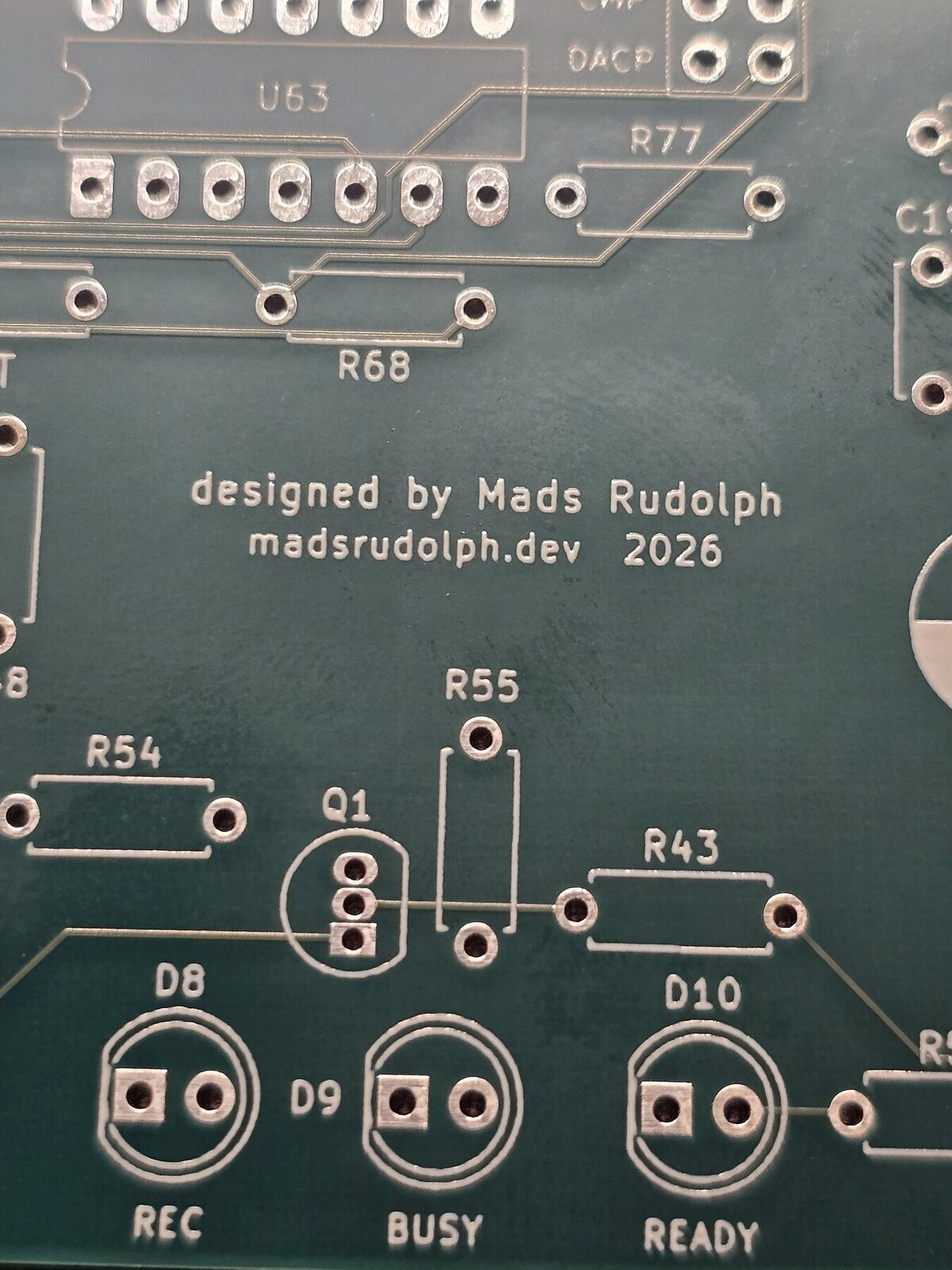
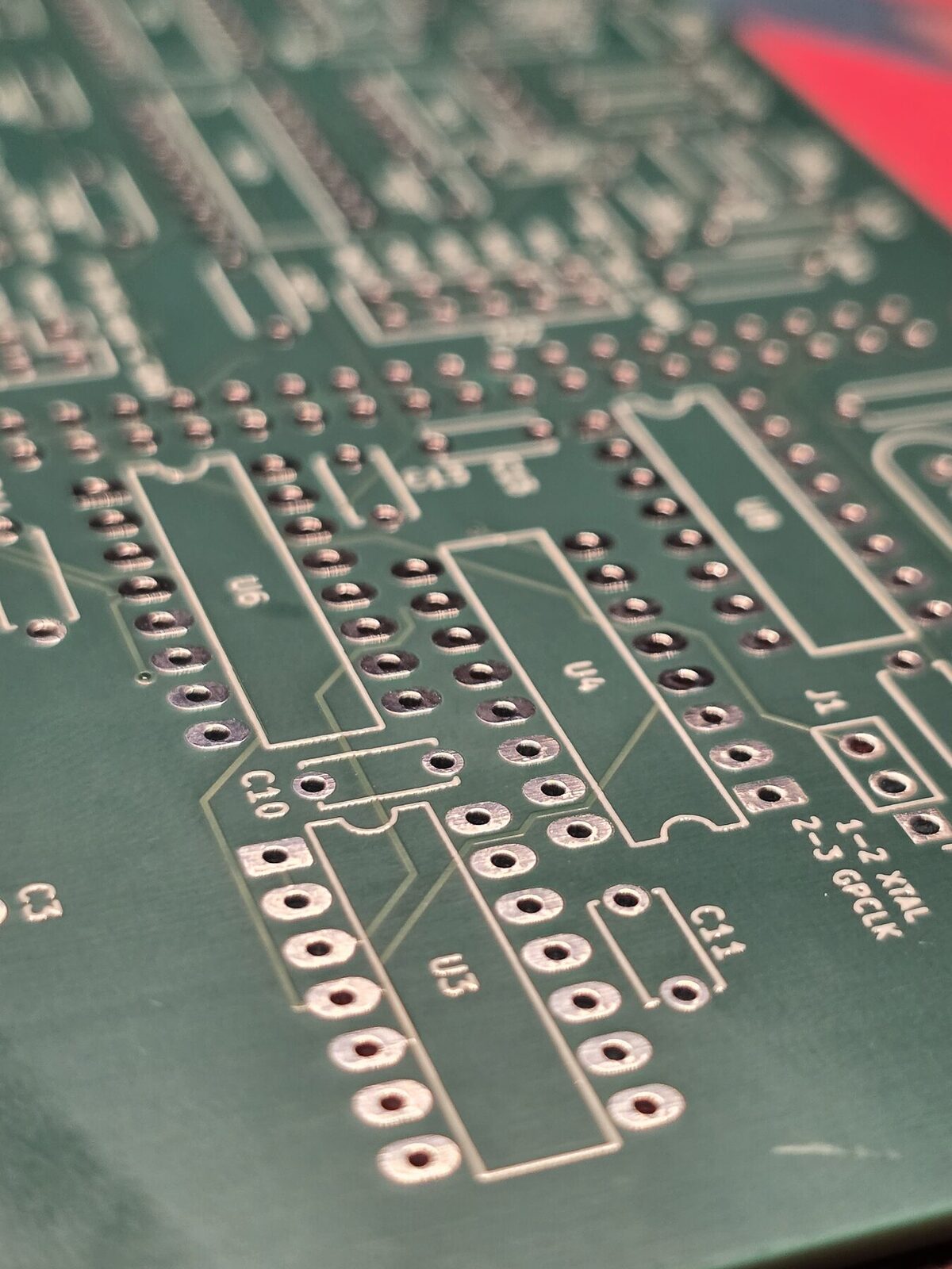
| Legends | 184 reference designators at 1 mm, the smallest labels 0.8 mm |
Why a fab board, for a converter
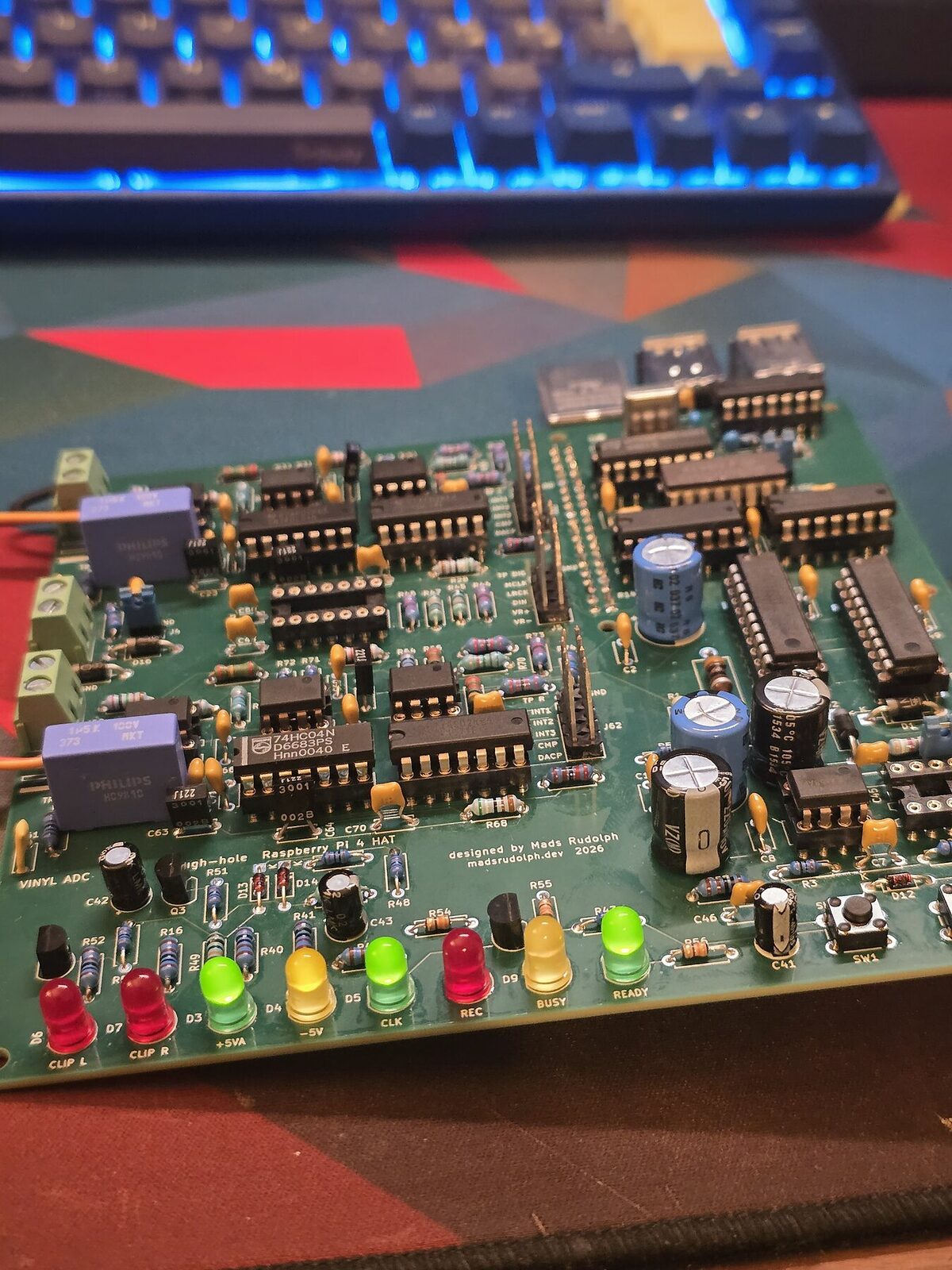
A delta-sigma modulator switches at 1.536 MHz right next to integrators that resolve microvolts. On one milled layer, ground was whatever copper was left between tracks; on rev D a whole inner layer is ground, under every signal. Every joint is soldered from one side and carried through by a plated barrel, so the fault that cost the most time in September cannot happen. And there are five identical boards, where every milled board was a one-off.
| Milled stack | Rev D by PCBWay | |
|---|---|---|
| Boards | 4 × 100 × 100 mm | 1 × 140 × 136 mm |
| Copper | 1 layer, milled | 4 layers, solid ground plane |
| Wire links | dozens | none |
| Bring-up | two days, two hidden faults | both channels healthy and matched at the first capture |
The record decides
Same turntable, same phono stage, levels set so music peaks at −6 dBFS on both builds, stylus lifted:
| 20 Hz–20 kHz | Milled stack, bench supply | Rev D, Raspberry Pi supply |
|---|---|---|
| Idle floor, A-weighted | −61.1 dBFS | −69.7 dBFS |
| Idle floor, 200 Hz–2 kHz | −68.6 dBFS | −73.7 dBFS |
| Idle floor, 2–20 kHz | −59.6 dBFS | −76.5 dBFS |
| Music to floor, A-weighted | 54.2 dB | 63.7 dB |
About 8 dB more range from the groove to the file, and a floor 5–17 dB lower above 200 Hz. Rev D does that on the supply that cost the milled boards the most, and these figures were taken on the Pi’s own clock, before its crystal was running. What remains is 50 Hz hum common to both channels, which is the turntable’s grounding rather than the converter; the board has a tonearm terminal for that next experiment.
On the bench
With its own crystal running, an Analog Discovery 3 generator into the input and the other input shorted:
| Milled stack, best channel | Rev D, left | |
|---|---|---|
| Dynamic range (AES17, A-weighted) | 67.9 dB | 78.7 dB |
| THD at −6 dBFS | 0.03 % | 0.019 % |
| Crosstalk | −92.4 dB | −97.8 dB |
That is 11 dB more dynamic range than the milled boards ever reached, and 10 dB past what the design was simulated for. The right channel measures 72.2 dB: it carries an extra in-band floor that the milled stack’s right channel had as well, now traced to its modulator loop and still being chased.
The one rev D fault found so far is mine, not the fab’s: two comparator inputs swapped in the schematic, which keeps both clip LEDs lit; the fix is two resistors on the underside. Full record: the rev D bring-up log and the rev D page of the bench guide.
An enclosure for rev D
Rev D gets a box of its own, shaped around the board rather than around a stack: 155 × 168 × 51 mm, a black PETG tray with the Raspberry Pi screwed to its floor and the HAT on three posts above it, a front plate that carries the controls, and a 3 mm laser-cut acrylic lid so the board stays on show.
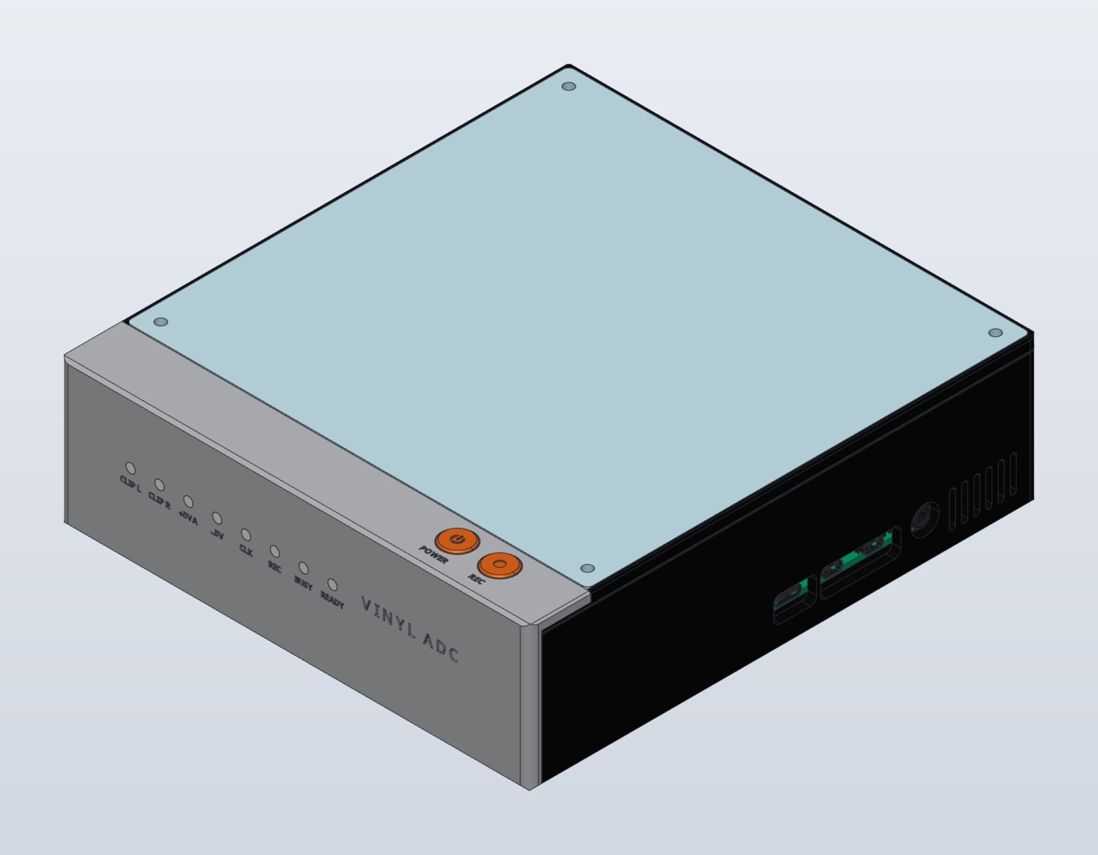
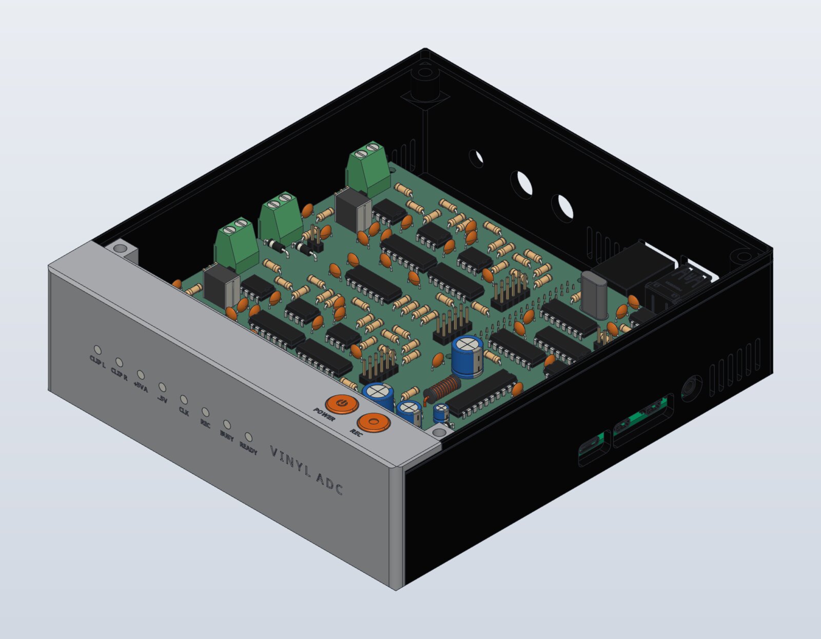
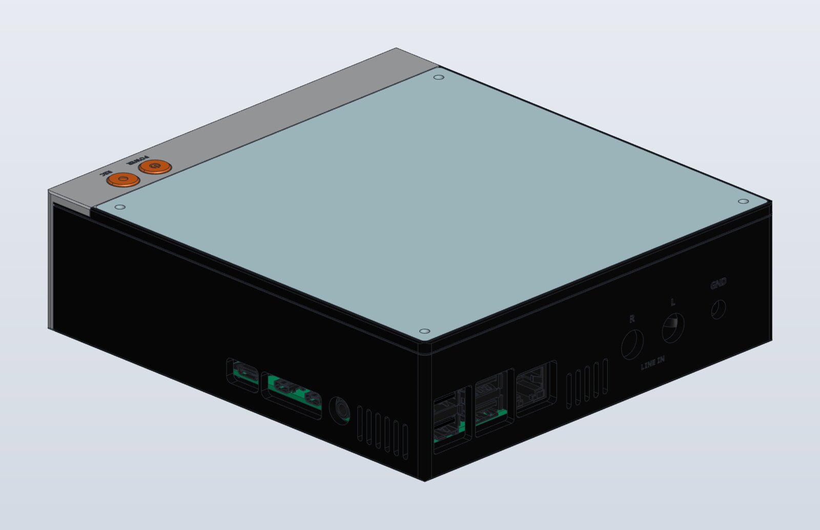
Every part was checked in CAD against the board’s 3D models and the Raspberry Pi’s, with real plugs in every port, before anything was printed; that check moved the port openings, the light-pipe walls and two pockets over the board’s screw heads. It has not been printed yet; that, and measuring the parts the models only estimate, come next.
Boards sponsored by PCBWay. Thank you for making the best version of this project possible.
The milled original
The challenge
Comparator delay limited the sampling rate. A third-order loop and delay compensation reached about 68 dB SNR in simulation. SPICE also caught a reversed charge pump that connectivity checks missed.
Measured results
The converter now runs in stereo and has been measured on the bench. The left channel came out within a fraction of a decibel of what SPICE predicted:
| Simulated | Measured | |
|---|---|---|
| SNR / dynamic range | ~68 dB | 67.9 dB |
| Frequency response, 20 Hz–16.3 kHz | — | ±0.06 dB |
| THD at −20 dBFS | — | 0.032 % |
| Crosstalk | — | −92 dB |
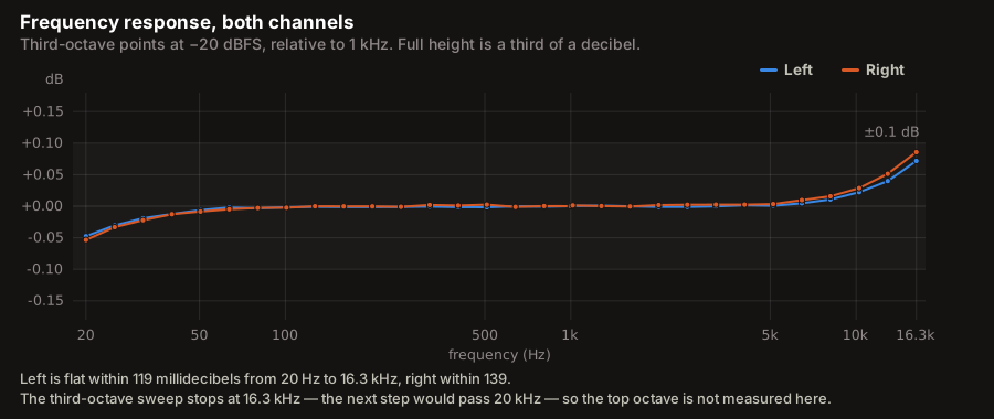
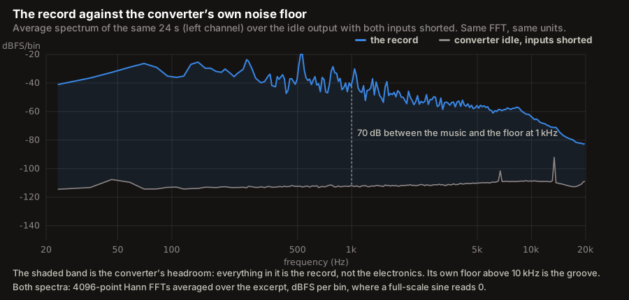
For a machine whose source is a record, the benchmark is the source: a good pressing delivers 60–70 dB, so the converter is not the limit. Signal generation was an Analog Discovery 3, whose own 14-bit generator bounds any distortion or noise figure near −80 dB — several of the intermodulation results sit at that floor and are measuring the instrument, not the converter.
How one bit gets there
The converter doesn’t measure the voltage. It compares, a million and a half times a second, and outputs a single bit each time — so the density of ones carries the signal, not their value.
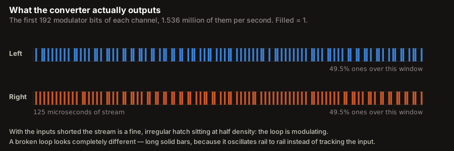
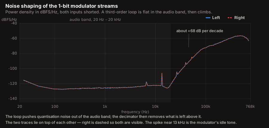
Trading resolution for speed that way produces an enormous amount of quantisation noise. The trick is that a third-order feedback loop doesn’t remove that noise, it moves it — out of the audio band and up into frequencies nothing needs, where the decimation filter discards it.
A record through it
Measurements with a signal generator say what the converter can do. This is what it did with a record on the turntable — the first side ripped end to end, as the ripper delivered it to the library.

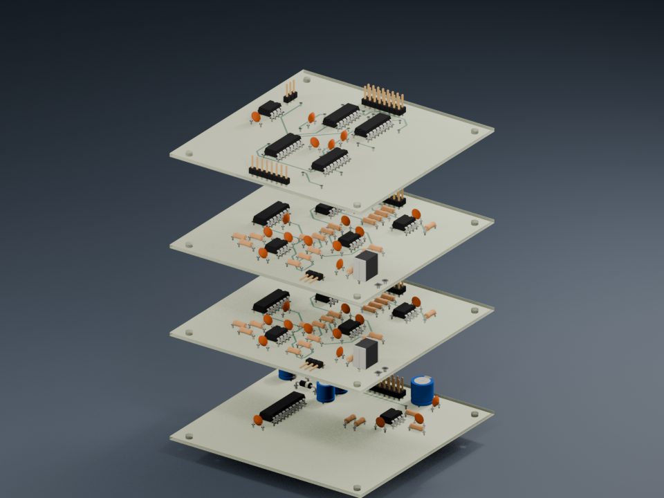
Getting there took finding two faults in the right channel that had hidden each other. Its negative supply reached the board only through solder that had wicked up an unplated hole beneath a connector body, where no iron can reach — the board’s own KiCad data showed ten connections that depend on a joint on the component side. Underneath that sat a short to ground on the feedback DAC’s output, which left the loop with no feedback at all: every integrator ran into the rails and the whole channel oscillated at 42 kHz. Both channels now shape noise identically at the bitstream level.
The measurement itself needed debugging before the hardware could be trusted. Because the ADC generates its own sample clock at 48009 Hz rather than exactly 48000, test tones landed about 190 ppm low and walked out of the analysis window in proportion to frequency — which looked convincingly like a steep analogue rolloff above 5 kHz, and wasn’t.
Status of the milled stack: Both channels work and are characterised. The right channel’s loop is provably identical to the left, but its input path costs it 9 dB of noise, with an intermittent level trimmer the leading suspect. Absolute input level, running from the Raspberry Pi’s own 5 V, and the enclosure as a physical print are still open. The full test and verification record covers the method, the instrument’s limits and everything not yet verified; the assembly guide and bench log include graphical probe connections and actual readings.
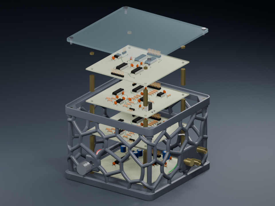
Printable enclosure for the milled stack
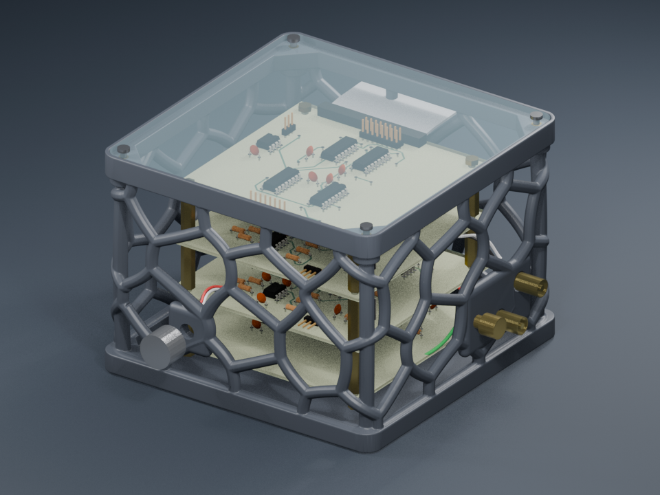
Rounded branches leave all four sides open so the boards remain visible. The enclosure is 144 × 144 × 105 mm, adding 40 mm for the taller stack and cable routing. Solid mounting islands surround the connectors. Thicker corner ribs support the four M3 heat-set lid inserts, while the original acrylic lid pattern is retained.
The mesh is a single watertight part and has been sliced with organic supports. Supports are required for the branch overhangs and upper rim; a successful slice is not a physical strength or fit test. The print package includes STL and 3MF files, reference print settings and a small insert-fit coupon. Board spacing in the animation is illustrative.
Download the enclosure and printing instructions · Download all three GIFs