Personal project. This rig turns the Analog Discovery 3 flywire cable into a reusable bench interface for circuit experiments and board bring-up, including my Vinyl ADC.
From flywires to a test fixture
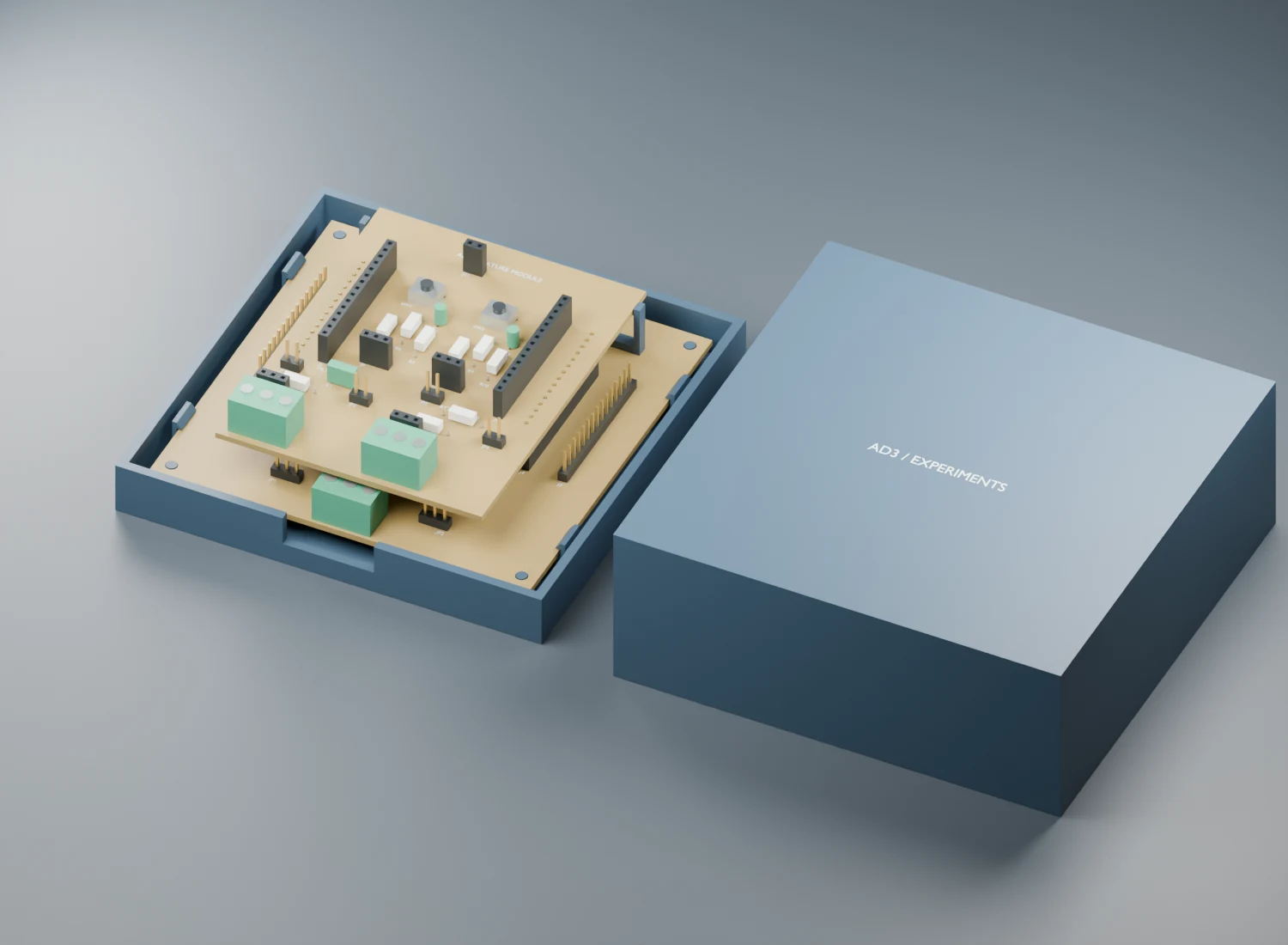
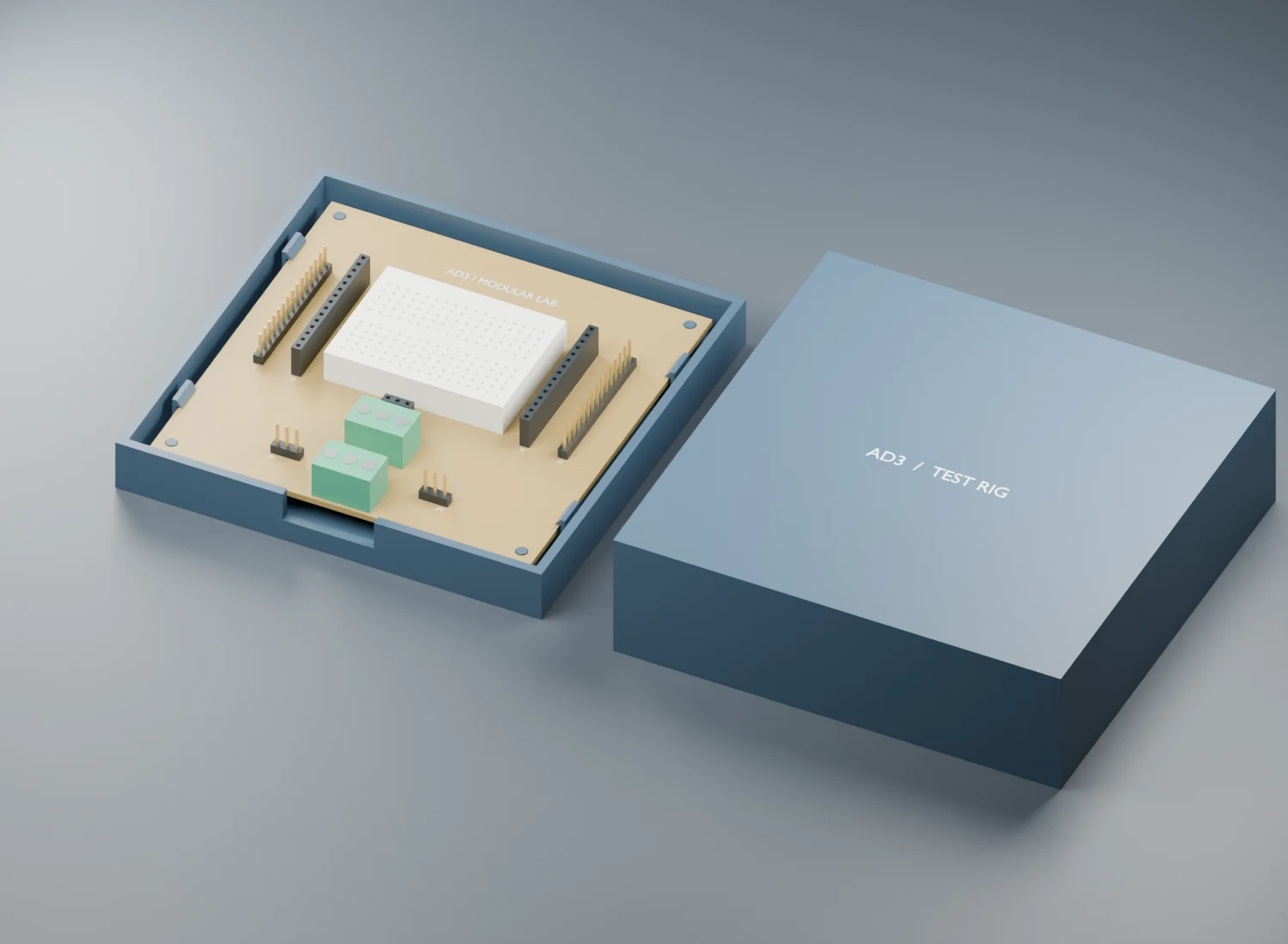
The 100 × 100 mm passive baseboard breaks out all 30 AD3 cable signals and adds selectable bench or instrument power connections. Its central space accepts a 170-point breadboard or a 70 × 90 mm plug-in module. Top sockets on the module keep every AD3 signal accessible.
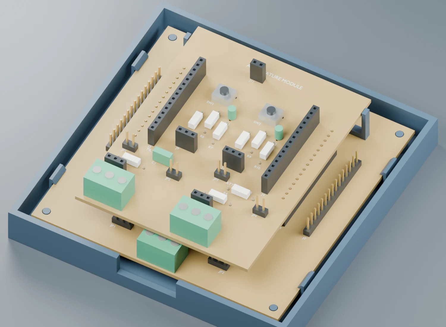
The module adds a nominal 1.59 kHz low-pass filter, an 11:1 attenuator, selectable loopback paths, screw terminals, two buttons and two LEDs. Experiments connect through patch wires, so each circuit can be tested independently. Purchased PCB components are matched to my component-shop CSV.
Designing for milling and assembly
Both boards use bottom-copper routing with 1.0 mm tracks, 0.85 mm global clearance and no vias. KiCad projects include local footprints, fabrication exports and assembly references. The enclosure is provided as editable Blender files and printable STLs.
A local dark-mode assembly guide connects reference designators to an interactive placement map, resistor colour codes and jumper settings. Python scripts use the WaveForms SDK to check analog gain and phase, then guide button and LED commissioning.
What the checks caught
The module’s four-leg tactile switches exposed a connectivity detail: each switch contains internally bonded pin pairs. A copper-only routing check reported gaps across those pairs. Modelling them explicitly in the KiCad footprints lets electrical checks account for the physical switch connections. The actual switch pin pairing still needs checking before assembly.
The underside male headers also need solder access. The assembly specifies a 1 mm gap below their plastic housings, with socket engagement and pin lengths to be confirmed against the actual parts.
Results and current status
- 49 automated module checks pass, covering inventory matching, connectivity, geometry, print meshes and simulated test failures.
- KiCad reports zero ERC and DRC violations, with no unconnected nets or schematic-to-board differences.
- SPICE responses agree with independent transfer-function calculations for the filter, attenuator and combined circuit.
- Commissioning scripts and wiring instructions are included; physical electrical tests and first-print fit are not yet complete.
Code, KiCad files, enclosure models & assembly instructions →